Type 2, Conclusions
Type 2: In-line power button enable/disable lock.
Click to enlarge!
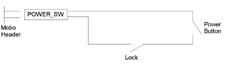
This type of key lock is more secure than the key-start, as the lock barrel is available in a standard key rather than a readily available key. What we are doing is creating a lock that is in-line with the power button, so that when the key is turned one way, the power button works as normal, and when its turned the other way, they button will not work at all. As they say, a picture tells a thousand words, so Ive included a quick diagram of what we will be making.
Click to enlarge!
As can be seen, when the key is moved to the ON position, the circuit becomes that of a normal power switch, and when the key is moved to the OFF position, the circuit is broken and the button will not work.
Parts needed:
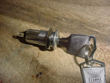
Lock (Jaycar part number SM1030)
Standard plastic coated wire
2 pin header block, attached to a standard momentary power button (such as the one currently in your case)
Soldering iron, solder, wire strippers (or teeth), wire cutters, heatshrink, lighter or matches.
Cut one of the wires coming from the two pin header block leading from the power switch roughly 5cm from the block. Strip 1.5cm of the coating away on each side. Now, figure out where you will be mounting the switch. I recommend a spare 5 ¼ inch bay.
As discussed in the previous guide, make sure you cut the hole leaving the correct grooves so that the barrel doesnt spin.
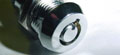
Fit the lock, securing it with the supplied nut. Once you have mounted the lock, measure the length of the cable you will be required to cut. You need to measure from the place where the lock is mounted to the 2 pin block. Once you have determined the length required, add 5cm and cut 2 pieces of wire this length. Strip back 1cm on each end of each wire you just cut.
OK, now remove the lock back out of the case. Solder the wires to the terminals leading out of the lock, and heatshrink them. Fit the lock back into the case.
OK, this is the point where we will be doing some in-case soldering. Remember, soldering irons are HOT! If you slip or drop one in your computer, it will kill components it lands on. So if you are not of steady hand, you may be wise to get a friend who is to do this.
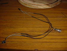
Solder one of the wires coming from the lock to the wire leading from the 2 pin block. Solder the other wire to the switch leading back to the power switch. Once you have shrunk down the heatshrink, turn the key, and press the power button. It should work fine.
Now turn the machine off, and turn and remove the key to its Off position. When you press the button now, you should get nothing.
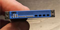
If you are not getting anything either way, chances are you have stuffed up the wire connections. This is what the final product should look like:
Click to enlarge!
Both of these modifications offer a low cost, easy to assemble computer security solution.
|