|
|
Advertisement:
|
|
DIY HTPC Remote Control |
|
Join the community - in the OCAU Forums!
|
Construction of the receiver and cable
Construction of the receiver and cable:
So, were going to have a small box containing the circuit and infra-red receiver, with a line coming out of the back going to a female DB9 connector. First, the parts:
  - 1-2m of 3+ core cable: here.
- 1 x DB9 backshell: here.
- 1 x DB9 female solder connector: here.
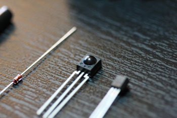
- 1 x 1N4148 diode: here.
- 1 x 4700 ohm resistor: here. (yellow, violet, red)
- 1 x 4.7uF capacitor: here.
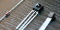
- 1 x 5mm infrared receiver: here.
- 1 x 78L05 voltage regulator: here.
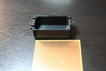
- 1 x HB6065 jiffy box: here.
- 1 x HP9540 circuit board: here.
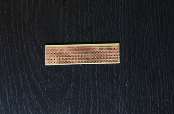
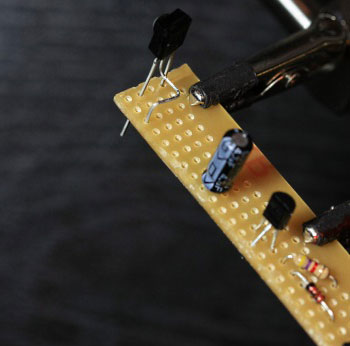
Cut the breadboard to size. Note that in each of the progress pictures here that the traces run horizontally, NOT vertically. Make the size of the breadboard wide enough to fit the box and cut it with either a saw or a dremel. A saws best suited for this job, really.
From here its a matter of soldering the components to the board, according to this schematic:
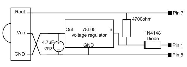
The schematic is actually based on a schematic on the lirc.org website. I should also note that there's a crossover on the left the wires are not joined there.
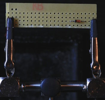
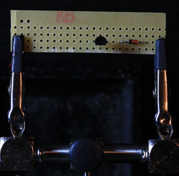
So, start by soldering the diode in place. Note the polarity (black strip on the middle instead of the edge):
With the voltage regulator, splay the legs of it so that with its writing towards you, push the side legs to each side a little, and pull the centre leg so its towards you.
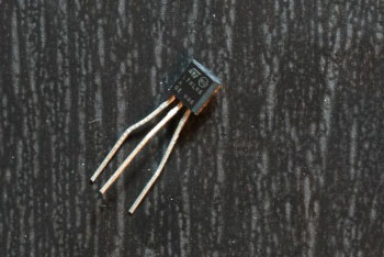
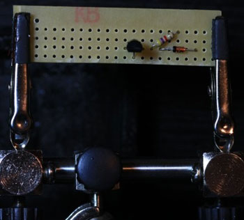
Place the voltage regulator as such:
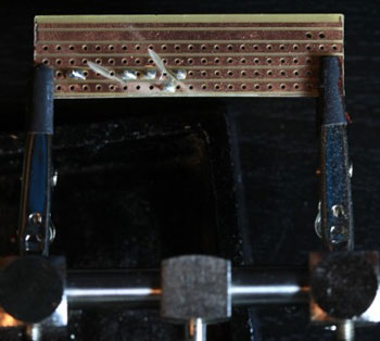
Then cut the traces below the diode and voltage regulator so that one pin of a component is not connected to another by the boards traces. I used a dremel for this I really shouldnt have used a cutting disc though:
Then the easy stuff add the resistor:
Then solder the capacitor with the side containing the white strip (negative pole) on the bottom:
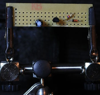
The IR diode needs its legs bent in a particular way, as the diode from Jaycar has a different pinout to the one in the lirc.org schematic. Note the way in which Ive bent the pins, and also what other components the pins line up with:
The diode is to be mounted offset on the edge of the circuit board so that the diode is as exposed as possible inside the jiffy box. Cut or drill a hole for the diode as appropriate. With your multicore wire, strip and tin the ends of three of the wires, and solder them to the circuit board as per the schematic on the locations DCD, Vcc and GND. On the other end of this cable, slide on the backshell (important!) Then strip, tin and solder the wires to the appropriate ports on the female DB9 solder connector.
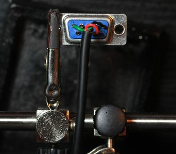
Solder DCD to pin 1, GND to pin 5 and Vcc to pin 7. Before you go any further, make sure everything is soldered correctly, that you have the correct polarity on the capacitor, and the correct polarity on the diode. Double check all of your connections, attach the backshell and plug it in. Also make sure you have your serial port enabled in the BIOS.
Variation: If your motherboard has an internal serial port header, then another option is to make this an entirely internal modification. Skip the making of a bracket and solder straight from the ribbon cable to the circuit board. Then drill a hole in the front of your case and affix the diode to face out through this hole.
Next: the software!
|
|
Advertisement:
All original content copyright James Rolfe.
All rights reserved. No reproduction allowed without written permission.
Interested in advertising on OCAU? Contact us for info.
|

|