|
|
|
|
|
ABIT AN7 |
|
Join the community - in the OCAU Forums!
|
Introduction, Layout
Today on the testbench we have a new motherboard from ABIT. This is a socket462 or socketA motherboard based on nVIDIA's nForce2 Ultra 400 chipset, which means it supports 400MHz FSB, dual-channel DDR400 memory and the latest AthlonXP and Duron processors.
The more alert among you may be thinking "Gosh Agg, this AN7 sounds a lot like the ABIT NF7-S v2.0 I have right here." You'd pretty much be right there, because based on spec-sheets alone (AN7 here, NF7-S v2.0 here), the two motherboards are very similar. However, if we look at the two boards side by side, we can see quite a few differences which add up to the AN7 being more than just an NF7-S v3.0 and deserving of a different name.
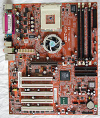 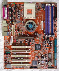
ABIT's NF7-S v2.0 (left) and AN7 (right)
In terms of basic layout they are very similar, but several things have been moved around and the AN7 has a few new features. The IDE connectors have been moved to the lower-right edge of the board, similar to the MAX series of motherboards. I wasn't too keen on this idea at first, but while using the AN7 I've become a fan of this location. Of course if you have a full-tower with your drives in the very top of the case (like above the PSU in an AOpen HX-08) then you will have some problems. However, the trend seems very much towards smaller cases nowadays and I find this layout makes for less cable mess than having them one above the other and horizontal like the NF7-S v2.0.
The orientation of the large ATX power plug has changed from horizontal to vertical. This is of no major significance, but I've heard a few complaints from people about putting the power connectors in this area at all. The main complaint is that the bulky bundle of power cables from the PSU to the motherboard passes right over the CPU cooling area, blocking airflow or interfering with watercooling pipes. The simple solution to my mind is to cabletie the thick ATX cable to the back of the case so that it runs along the bottom of the PSU, down the inside back of the case and to the socket. A single small nylon zip-tie can be used for this purpose and clears up that whole area. The 4-pin cable can be routed the same way because that socket is right next to the main ATX one.
One annoyance about the NF7-S is the placement of the CPU socket right on the very top edge of the motherboard. In a small tower this can make installing or removing a CPU cooler which attaches to the socket lugs very fiddly. In many cases you literally have to remove the PSU to get access to the CPU cooler mount. This location unfortunately has not changed on the AN7. The location of capacitors near the socket will also annoy people who ran into problems with the NF7-S, as we did in our WaterChill review, as they have not been moved or replaced by shorter components.
Another common complaint involves the RAM slots being fouled by a video card in the AGP slot. Again on the AN7 we see this problem, but I will grant that ABIT have the RAM slots near the far edge of the board and instruct you to fill DIMM3 first, which is almost as far from the AGP slot as possible. Neither the PowerColor R9800 Pro or Leadtek GF3 TDH used for testing actually fouled any of the RAM slots as they are too short. Longer cards such as the high-end GeForce FX cards may have this issue, though.
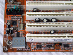
Another interesting feature is the small double-digit LED at the bottom left of the AN7. I don't recall seeing this feature on an ABIT motherboard before. From memory the first manufacturer to provide such a diagnostic display was MSI, and recent EPoX boards have had them too. They can be handy for troubleshooting booting problems, but I found the two most common error codes I received during overclocking testing were not listed in the manual.
Note that the NorthBridge cooler is on a 3-pin connector now, which means it can be monitored and have its speed controlled by the BIOS or software. This is a welcome change from the earlier motherboard. Including the one powering the NorthBridge fan there are 5 fan connectors in total, up from 3 on the NF7-S. The BIOS chip is socketed on both boards so it can be changed in case of disaster. Both boards have a clearly-labelled CCMOS (Clear CMOS) jumper with an easy-grip jumper cap on it in case you really confuse the board and need to go back to defaults. It amazes me that many motherboards still lack this vital overclocking safety-net. The CMOS battery is mounted flat against the board to lessen the risk of shipping damage as we've seen previously. Be cautious when mounting 5.25" devices into a small case with this motherboard, as installed DIMMS or a tall capacitor near the top right of the board could be damaged by the back of a CDROM drive if it is forced into the case.
One of the complaints about the NF7-S v2.0 was about voltage stability at high FSB and high VCORE (CPU voltage). ABIT seem to have changed the power-regulation components on the AN7, but I am unfortunately not in a position to be testing super-high core voltage due to the cooling I have available.
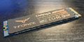
There's been a lot of talk about a cut trace on the back of early AN7 samples. The board we received did indeed have the cut trace which you can see in the picture below.
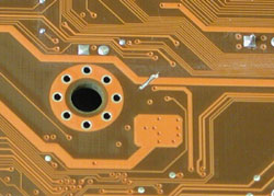
To my mind this is not such a big deal. It's no different really to the small peices of wire or other minor modifications we see on motherboards or video cards from time to time. This particular cut attracted attention because people thought it may have been accidental or shipping damage, but it seems that all the early boards had an identical cut. I asked ABIT for their explanation of this cut - the response was: The AN7 you have was the first lot of engineering samples. The cut on AN7 has no effect to the board so won't effect your review. The proof of the pudding will be in the testing, regardless. There are reports now that the more recent retail boards do not have this cut.
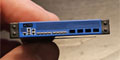
One very strange thing I noticed was that the silkscreening (the writing on the PCB itself) wrongly labels the Power-On switch on the block of front-panel connections. You can see in the picture below that it seems to indicate the bottom left two pins are for Power-On, when in fact it is the top-right two pins of the leftmost block, above the two marked RST, the same as on the NF7-S.
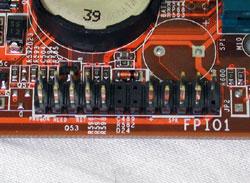
This mislabelling could be disastrous. Fortunately I was suspicious about the need to change the layout of this jumper-block from the NF7-S, so checked the AN7's manual and found that the pins were mislabelled on the board. Hopefully this will be corrected in future revisions.
|
|
Advertisement:
All original content copyright James Rolfe.
All rights reserved. No reproduction allowed without written permission.
Interested in advertising on OCAU? Contact us for info.
|
|