|
|
|
|
|
Selecting core voltage on -any- Slot1 board! |
|
Join the community - in the OCAU Forums!
|
 |
|
Slartibartfast sent some amazing info on setting voltage on ANY slot-1 board! Now, I haven't tried this, and obviously neither Overclockers Australia or Slartibartfast can be held reponsible if you blow up your gear while trying this, but it's DEFINITELY something to think about!
When looking for a new BX board for overclocking I steered clear of ABIT because of stability problems when using cheap RAM. I had problems with an ABIT PX5 when using more than one SIM and high bus speeds, and read plenty of reports about similar problems with BX6 and BH6.
I settled on the AOPEN AX6BC and thought pin taping would get over the lack of voltage adjustment. My board runs stable at 117 FSB with 3 cheap PC 66 ram. I then decided to solder wires and switches to the pins of the motherboard and processor to allow easy adjustment of voltages.
While trying this I came up with an easy method of allowing all core voltages 1.80-3.5 on any slot one board. To understand how this works you must know how the pins select the voltage. Voltage is selected by pins VID0 - VID4. These pins can either be open (not connected to anything) or earthed (connected to Vss - motherboard earth). The processor VID pins are connected to Vss or left open when the processor is made, a different combintion for each voltage, allowing it to tell the MB what voltage it needs, taping allows us to open an earthed pin thus giving the alternative voltages 2.2, 2.4 etc.
OK so the MB reads the processor VID pins and sets the voltage, why not bypass the CPU pins completely and fool to MB into giving us any core voltage. This is more simple than it sounds.- Tape all VID pins on the processor (A119, A120, A121, B119, B120)
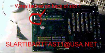
- Solder a thin wire to the terminals of the motherboard which contact the VID pins. An easy way to do this is to turn the MB over locate the correct pins where they come through the back of the MB and tack your wires onto the lumps of solder there.
- Solder a thin wire onto any pin on the slot 1 of the MB which is connected to Vss (ground) I used A118 (use same method as above)
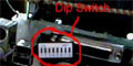
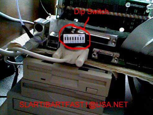
- Get a small set of dip switches (at least 5 switches). Each switch on the dip switches has two terminals. Connect the terminal on the "ON" side of five of the switches together (solder a wire across them all). Now solder the wire from pin A118 to these "ON" terminals.
- Connect each VID pin wire to one of the switch terminals at the "OFF" side of the switch. Remember which switch number is connected to which VID pin. So now when a switch is on the corresponding VID pin is earthed (connected to Vss) and when the switch is off the VID pin is open (not connected to anything).
- Put some blue tac or something over your solder joints on the bottom of the MB.
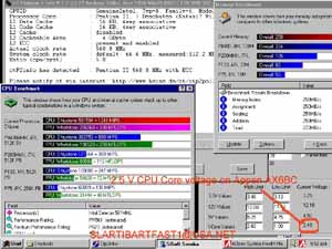
If all goes well by checking the intel specs VID pin table you can set any VID pin to be open or earthed and so set any CPU core voltage.
Click this last picture for a larger view..
I'm in Aus despite my email address. Have fun melting those chips
This article originally appeared here.
|
|
Advertisement:
All original content copyright James Rolfe.
All rights reserved. No reproduction allowed without written permission.
Interested in advertising on OCAU? Contact us for info.
|
|