|
|
Advertisement:
|
|
CoolerMaster AquaGate Liquid Cooling System |
|
Join the community - in the OCAU Forums!
|
Inside the LCU
Inside the LCU:
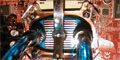
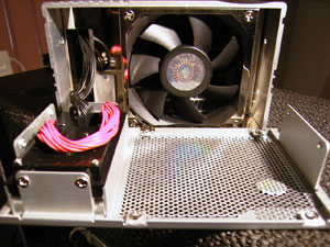
After undoing four screws, the front grille and LCD module mount slide forward and out, exposing the 80mm fan positioned to blow air into the radiator. There is no included air filter, but the inside of the LCU is fairly accessible and it should not be too difficult to clean every now and then. The close-punched holes in the LCUs grille look attractive, but unfortunately the airflow especially at higher fan speeds causes an increase in the noise generated by the AquaGate.
I found that the grille is a tight fi, and it can also be a little difficult to get back in place with the wires behind the LCD tending to get in the way. The LCD includes two temperature displays: the CPU temperature, as measured by the included thermal probe, and the water temperature, as measured by the probe positioned inside the water reservoir.
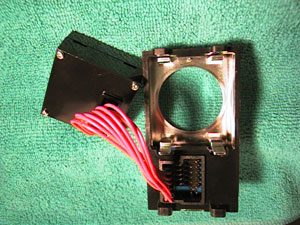
When the front grille of the Liquid Cooling Unit has been removed, 4 more screws hold the LCD module in place. If the LCU is to be used externally, or mounted in a secondary power supply bracket, the LCD unit can be attached to the included face-plate and installed in a 5.25 CD bay. The actual LCD screen is held in place by a small clip, so it can be easily rotated to accommodate the different mounting options. CoolerMaster have also included a spacer block that replaces the LCD in the LCU so that its attractive look is maintained.
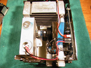
This picture was taken after our testing procedure had been completed; the LCU unit is filled with coolant.
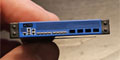
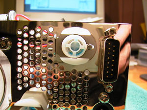
At the rear of the LCU are two non-leaking connector ports, the D-bus cable connector, a two-prong AC power socket and an 60mm fan grill air outlet. The D-bus connector is used to connect the internal circut board and hence the LCD and related controls to the internal PCI card. The D-bus cable also supplies power to the LCD unit and intake fan. The internal circut board, LCD and controls are the brains of the AquaGate and the system will not function if the D-bus cable is not plugged in.
The pump is powered by an external power cable and uses either a 110V straight-through power cable or a 220V power adapter cable (both supplied). The pumps power cord actually uses a pass-though connector; the power cord is plugged into the computer's power supply, and then the power supplys cord is piggy-backed onto the pump cord. Interestingly this power socket is only used to power the pump and nothing else inside the LCU. If the power to the pump is removed the AquaGate will continue to function until the alarm temperature is reached and it shuts the system down.
CoolerMaster do not provide any specifications on the pump, other than to indicate it is powered by 110V and that it draws 9W. However the fact that is a high voltage AC pump should make it more reliable than a 12V DC pump that would have been required if there was no external power connector.
Again, taken after our testing procedure was finished - the blue coolant can easily be seen.
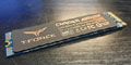
Four additional screws can be undone to remove the brushed aluminium cover from the Liquid Cooling Unit and expose its inner workings. Liquid is drawn in through the top intake, through the radiator and into the reservoir. A larger fitting is used to connect the pump intake to the reservoir before the water is pumped out the bottom connector. The radiator and reservoir are actually a single combined unit, which appears to be made from aluminium.
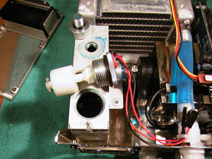
The reservoir is actually full of coolant in this picture, and while the level looks low, it rises considerably when the probe and float are installed.
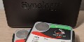
The LCUs reservoir has two top mounted metal screw-in plugs. The smaller plug is used to fill the reservoir with coolant, and a cut-out in the aluminium cover means that this can be accomplished without disassembling the unit. The larger plug, which is hidden when the LCU is assembled, holds the water temperature probe and water level float.
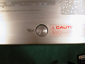
Note the scuff marks caused by the screwdriver when opening and closing the coolant tanks plug.
Unfortunately, I found that when the Liquid Cooling Unit was assembled, the water inlet plug did not fit centrally over the hole cut into the LCUs aluminium cover. This made opening or closing the plug a little difficult as it tended to grind on the aluminium cover as it was screwed open or closed.
|
|
Advertisement:
All original content copyright James Rolfe.
All rights reserved. No reproduction allowed without written permission.
Interested in advertising on OCAU? Contact us for info.
|

|