|
|
|
|
|
DIY HTPC Remote Control |
|
Join the community - in the OCAU Forums!
|
Introduction, Tools, Getting a serial port
After having reinstalled my home theatre PC after a hardware upgrade, I looked at ways I could improve it. I had a reasonably stealthy setup a Lian Li PC-C36B, wireless mouse, and a black keyboard which sat in the coffee table. It was flexible, but at the same time a bit awkward for when I just wanted to do simple tasks like play a TV episode or movie. I saw big advantages in not having to drag out the keyboard/mouse every time I wanted to watch something.
My HTPC has a Fusion HDTV Pro card, which comes with its own remote control and receiver. Unfortunately the actual provided control by the remote and receiver is limited to within the Fusion HDTV software alone.
The options from this point became:- Buy an MCE remote package (around $70) and use the included software to control the computer.
- Buy a premade IR receiver, and buy/set up IR software.
- Make my own IR receiver, find some free software.
With a bit of reading and experimentation, Ive managed to find a low cost solution to the problem and as with such solutions, theres a bit of DIY involved. This wont be a short article, but at the same time, its not going to be big on the specifics - cable lengths, PCB sizes and the like that sort of thing will be up to you.
All of the parts specified by this article are purchasable from Jaycar Electronics. The various tools etc are also purchaseable from them if necessary, but will dramatically increase the cost. If you have to actually go and purchase a soldering iron just to undertake this project, then you may as well just purchase something premade.
Software requirements are split into two parts:
- A program to receive and interpret the signals.
- A program to translate the received signals into actions.
Software such as LIRC/WinLIRC/Girder will fulfil the first role, and some programs are written with support for the latter Media Player Classic, WinAmp, etc. Infrared support in programs is typically limited if they have such support at all. Luckily, HIP (Human Interface Programmer) will replace the need for a program to have infrared support.
So, the aim of this article is to get you set up with a fully functioning IR setup on the cheap. Theres work involved, but if youre like me then youll be all over the DIY stuff and will ultimately have the satisfaction of a working setup youve made yourself. Ill skip all of the research I had to do and just summarise it in links at the end. So, to work!
Tools required:
Tool requirements are fairly basic:- Soldering iron
- Solder
- Wire stripper
- Hot glue
If you need to build a serial port bracket, you will also need:Getting a serial port:
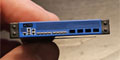
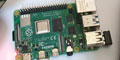
To do this, youre going to need a serial port. If you have a serial port on the rear of your PC, then skip this part, and move on to the construction section. However, it's no longer common for modern motherboards to have an external serial port connector. My motherboard is an ASUS M4A88TD-Pro USB3, which lacks an external serial port plug, but fortunately has one of these:
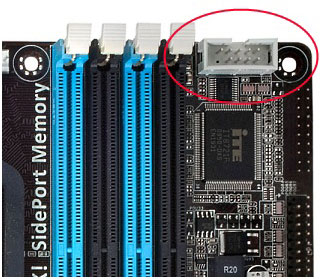
An onboard serial port header!
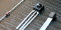
Here we need four parts:- An IDC line socket: here
- A short length of ribbon cable: here
- A male DB9 solder connector: here
- An expansion bracket.
You probably already have the first two have lying in a parts box somewhere. Remember this guy?
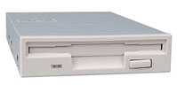
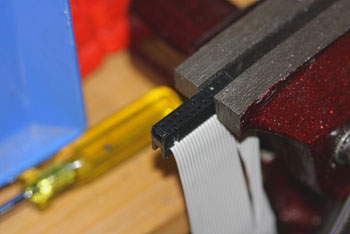
Well, we dont want the drive, we just want its cable chances are that your motherboard came with one of those but its been resigned it to a life of filling your motherboards original box to keep the IEEE1394 header company. So, take the cable and split it so that you have 9 wires. Then cut the plug end so that you have a 5x2 cluster as shown in the next picture. Try to get the end of the cable with the red wire this is the #1 wire. I just used a dremel, but a saw will also do the job nicely.
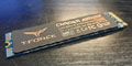
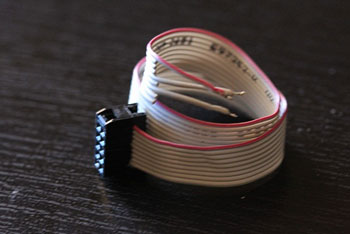
Glue the cap to make sure that it cant come off. Strip and tin wires 1, 5 and 7 on the other end of the ribbon cable. Ignore the rest of the wires we will not need them. You should now have something resembling the following:
On the other end, solder on each of the wires of the pin block onto the corresponding pins of the DB9 male solder plug:- Pin 1: CD (carrier detect)
- Pin 5: GND (system ground)
- Pin 7: RTS (request to send/ready to send)
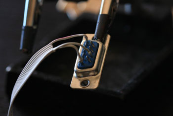
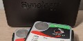
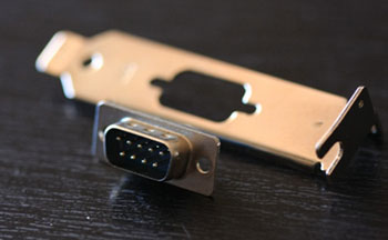
Cut an expansion bracket which would accommodate the DB9 connector a dremel may be useful for this. Now either hot glue or rivet the DB9 to the bracket youll need to drill holes if you take the route of riveting. You should end up with something that looks like this but hopefully neater as you havent used old parts youve salvaged from a box!
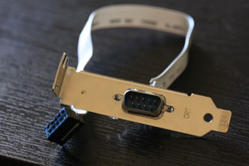
Mount this into your PCs chassis. Next up we'll build the receiver itself, then move onto the software side of things.
|
|
Advertisement:
All original content copyright James Rolfe.
All rights reserved. No reproduction allowed without written permission.
Interested in advertising on OCAU? Contact us for info.
|
|